Table of Contents (tap to open/close)
Electric Current and Circuit
Electricity is very important in our lives. It powers homes, schools, hospitals, and industries. But what is electricity and how does it work? Let’s find out.
Electric Current and Circuit
- Electric Current:
- Just like water flows in a river, electric charge flows through a conductor (like a wire) and creates an electric current.
- Example: In a torch, the battery provides the charge flow that lights the bulb.
- Electric Circuit:
- A continuous and closed path for electric current is called an electric circuit.
- If the circuit is broken (like when the torch switch is off), the current stops, and the bulb doesn’t glow.
- Measuring Electric Current:
- Electric current is the amount of charge flowing through a specific area in a unit of time.
- In circuits, electrons (negative charges) flow, but we consider the current direction opposite to electron flow.
- Formula:

- 𝐼 is current
- 𝑄 is charge
- 𝑡is time
- Units:
- Charge is measured in coulombs (C).
- Electric current is measured in amperes (A).
- Smaller units: milliampere (mA) and microampere (µA).
- 1 A = 1 C/1 s.
- Ammeter:
- Measures electric current in a circuit.
- Connected in series in the circuit.
Example 11.1
- Problem: A bulb draws 0.5 A for 10 minutes. Find the charge.
- Solution:
- Current, 𝐼=0.5A
- Time, 𝑡=10min = 600 s
- Charge, 𝑄=𝐼×𝑡=0.5×600=300 C
Electric Potential and Potential Difference
- Electric Potential Difference:
- Charges flow in a wire if there is a potential difference, like water flows due to pressure difference.
- A battery creates this potential difference.
- Definition:
- The potential difference between two points is the work done to move a unit charge from one point to the other.
- Formula:

- 𝑉Vis potential difference
- 𝑊 is work done
- 𝑄 is charge
- Units:
- Potential difference is measured in volts (V).
- 1 V = 1 joule/1 coulomb.
- Voltmeter:
- Measures potential difference.
- Connected in parallel across the points to be measured.
Example 11.2
- Problem: How much work to move a 2 C charge across a 12 V potential difference?
- Solution:
- Charge, 𝑄 = 2 C
- Potential difference, 𝑉 = 12V
- Work, 𝑊 = 𝑉×𝑄 = 12×2 = 24 J
Circuit Diagram
- Electric Circuit Components:
- A typical electric circuit includes a cell (or battery), a plug key, electrical components, and connecting wires.
- We use symbols to represent these components in a schematic diagram for simplicity.
Ohm’s Law
- Relationship Between Potential Difference and Current:
- There’s a relationship between the potential difference (voltage) across a conductor and the current flowing through it.
Activity 11.1: Exploring Ohm’s Law (click here)
- Setup:
- Circuit with nichrome wire, ammeter, voltmeter, and 1.5V cells.
- Procedure:
- Start with one cell, note the ammeter (current) and voltmeter (voltage) readings.
- Repeat with two, three, and four cells.
- Calculate the ratio of voltage to current (V/I) each time.
- Observation:
- The ratio 𝑉/𝐼 is constant, showing a straight-line graph through the origin.
- This constant ratio indicates Ohm’s law: 𝑉∝𝐼.
- Ohm’s Law:
- Formula: 𝑉=𝐼𝑅
- 𝑉: Potential difference
- 𝐼: Current
- 𝑅: Resistance
- Resistance (R):
- It is the property of a conductor to resist the flow of charges.
- Measured in ohms (Ω).
- 𝑅=𝑉𝐼
- Example:
- If 𝑉=1V and 𝐼=1A, then 𝑅=1Ω.
- Current and Resistance:
- 𝐼=𝑉/𝑅
- Current is inversely proportional to resistance. If resistance doubles, current halves.
- Formula: 𝑉=𝐼𝑅
- Variable Resistance and Rheostat:
- To control current without changing the voltage source, we use variable resistance or a rheostat.
Activity 11.2: Understanding Resistance
- Setup:
- Circuit with a nichrome wire, torch bulb, 10W bulb, ammeter, plug key, and connecting wires.
- Procedure:
- Connect four 1.5V cells in series with an ammeter and leave a gap XY.
- Complete the circuit with different components in gap XY (nichrome wire, torch bulb, 10W bulb) and note ammeter readings.
- Observation:
- Different components give different ammeter readings.
- This indicates different resistances for different materials.
- Why Currents Differ:
- Components either facilitate or resist electric current flow.
- Good Conductors: Low resistance, easy path for current.
- Resistors: Higher resistance, hinder current flow.
- Poor Conductors and Insulators: Even higher resistance.
These activities and concepts help us understand how electric circuits work and the importance of resistance in controlling electric current.
Factors Affecting Resistance of a Conductor
Activity 11.3: Observing Resistance
- Setup:
- Electric circuit with a cell, ammeter, nichrome wire (length 𝑙), and a plug key.
- Procedure:
- Plug the key and note the current.
- Replace with a nichrome wire twice the length (2𝑙) and note the current.
- Use a thicker nichrome wire of the same length and note the current.
- Use a copper wire of the same length and cross-section as the first nichrome wire and note the current.
- Observations:
- Longer wire (2𝑙): Current decreases.
- Thicker wire: Current increases.
- Different material (copper): Current changes.
Factors Affecting Resistance
- Conclusion (Concepts):
- Resistance depends on:
- Length of the conductor (𝑙): 𝑅∝𝑙
- Cross-sectional area (𝐴):

- Material of the conductor.
- Resistance depends on:
- Combining Factors:

- 𝜌ρ (rho) is the resistivity of the material.
- Resistivity:
- SI unit: Ω meter (Ωm).
- Metals have low resistivity; good conductors.
- Insulators have high resistivity.
Examples
- Example 11.3: Calculating Current
- (a) Electric Bulb:
- Voltage (𝑉) = 220V, Resistance (𝑅) = 1200 Ω.
- Current (𝐼) = 𝑉/𝑅=220𝑉/1200Ω=0.18𝐴.
- (b) Electric Heater:
- Voltage (𝑉V) = 220V, Resistance (R) = 100 Ω.
- Current (𝐼) = 𝑉/𝑅=220𝑉/100Ω=2.2A.
- (a) Electric Bulb:
- Example 11.4: Changing Voltage
- Initial: 𝑉=60𝑉, 𝐼=4A.
- Resistance (𝑅) = 𝑉/𝐼=60𝑉/4𝐴=15Ω.
- New Voltage: 𝑉=120𝑉.
- New Current (𝐼) = 𝑉/𝑅=120𝑉/15Ω=8A.
- Example 11.5: Calculating Resistivity
- Given: 𝑅=26Ω, 𝑑=0.3𝑚𝑚=0.0003𝑚, l=1m.

- 𝜌=1.84×10⁻⁶Ω𝑚 (Resistivity of manganese).
- Example 11.6: Comparing Wires
- First wire: 𝑅1=4Ω.
- Second wire: Length (𝑙/2), Area (2𝐴).

These activities and examples demonstrate how the resistance of a conductor is influenced by its length, cross-sectional area, and material.
Resistance of a System of Resistors
- Resistors can be combined in various ways in electrical circuits.
- Understanding how resistors combine helps in applying Ohm’s law to these combinations.
1. Resistors in Series
- Series Connection:
- Resistors are connected end to end.
- The same current flows through each resistor.
Activity 11.4: Current in Series
- Connect three resistors in series with a battery, ammeter, and plug key.
- Observe the ammeter reading at different positions.
- Conclusion: Current remains the same throughout the series circuit.
Activity 11.5: Voltage in Series
- Connect a voltmeter across the ends of the series combination.
- Measure the voltage across each resistor and the total combination.
- Conclusion: Total voltage 𝑉 is the sum of individual voltages 𝑉1,𝑉2,𝑉3.
- Formula: 𝑉=𝑉1+𝑉2+𝑉3.
- Current & Voltage in Series
- Conclusion: Current remains the same throughout the series circuit.
- Total voltage 𝑉 is the sum of individual voltages 𝑉1,𝑉2,𝑉3.
- Formula: 𝑉=𝑉1+𝑉2+𝑉3.
- Equivalent Resistance in Series:
- The total resistance 𝑅𝑠 is the sum of individual resistances 𝑅1,𝑅2,𝑅3.
- Formula: 𝑅𝑠=𝑅1+𝑅2+𝑅3.
- Example 11.7: Series Circuit Calculation
- Given: Electric lamp (20 Ω), Conductor (4 Ω), Battery (6V).
- Total Resistance: 𝑅𝑠=20Ω+4Ω=24Ω.
- Current: 𝐼=𝑉/𝑅𝑠=6𝑉/24Ω=0.25𝐴.
- Voltage across lamp: 𝑉1=20Ω×0.25𝐴=5𝑉.
- Voltage across conductor: 𝑉2=4Ω×0.25𝐴=1𝑉.
2. Resistors in Parallel
- Parallel Connection:
- Resistors are connected between two points.
- Voltage is the same across each resistor.
Activity 11.6: Current in Parallel
- Connect three resistors in parallel with a battery, ammeter, and voltmeter.
- Measure the current through each resistor.
- Conclusion: Total current 𝐼 is the sum of individual currents 𝐼1,𝐼2,𝐼3.
- Formula: 𝐼=𝐼1+𝐼2+𝐼3.
- Current in Parallel
- Conclusion: Total current 𝐼 is the sum of individual currents 𝐼1,𝐼2,𝐼3.
- Formula: 𝐼=𝐼1+𝐼2+𝐼3.
- Equivalent Resistance in Parallel:
- The reciprocal of total resistance 𝑅𝑝is the sum of reciprocals of individual resistances 𝑅1,𝑅2,𝑅3.
- Formula:
- Example 11.8: Parallel Circuit Calculation
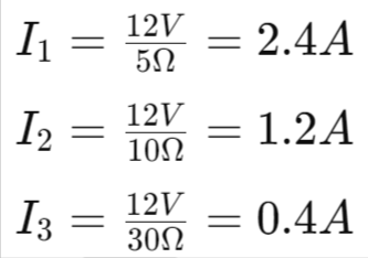
- Given: Resistors (5 Ω, 10 Ω, 30 Ω), Battery (12V).
- Current through each resistor:
- Total current: 𝐼=2.4𝐴+1.2𝐴+0.4𝐴=4A.
- Total resistance: 𝑅𝑝=3Ω.
Key Takeaways
- Series Circuits:
- Same current through all resistors.
- Total resistance is the sum of individual resistances.
- Total voltage is the sum of voltages across each resistor.
- Parallel Circuits:
- Same voltage across all resistors.
- Total current is the sum of currents through each resistor.
- Reciprocal of total resistance is the sum of reciprocals of individual resistances.
- Practical Use:
- Series circuits are impractical for devices needing different currents.
- Parallel circuits are preferred for multiple devices as they allow different currents and lower total resistance.
Heating Effect of Electric Current
- Electric Energy Source: A battery or cell provides electrical energy. It generates a potential difference that moves electrons and creates current.
- Energy Use: The energy from the source does two things:
- Useful Work: E.g., rotating a fan’s blades.
- Heat: Some energy turns into heat, making gadgets warm.
- Heating Effect: In a purely resistive circuit (only resistors), all the source energy turns into heat. This is called the heating effect of electric current. Used in:
- Electric heaters
- Electric irons
Calculations
- Power Input: Power 𝑃 is given by:𝑃=𝑉𝐼
- Heat Produced: Heat 𝐻 in time 𝑡 is:𝐻=𝑉𝐼𝑡=𝐼2𝑅𝑡
- This is Joule’s Law of Heating.
Example 11.10
- Electric Iron at Maximum:
- Power: 840 W
- Voltage: 220 V
- Current: 𝐼=840𝑊/220𝑉=3.82A
- Resistance: 𝑅=220𝑉/3.82𝐴=57.60Ω
- Electric Iron at Minimum:
- Power: 360 W
- Voltage: 220 V
- Current: 𝐼=360𝑊/220𝑉=1.64𝐴
- Resistance: 𝑅=220𝑉/1.64𝐴=134.15Ω
Example 11.11
- Heat Produced: 100 J each second in a 4 Ω resistor
- Current:

- Potential Difference: 𝑉=𝐼𝑅=5𝐴×4Ω=20𝑉
- Current:
11.7.1 Practical Applications of Heating Effect
- Devices:
- Electric iron, toaster, oven, kettle, heater
- Electric Bulb: Uses heating to produce light. Tungsten filament is used.
- Fuse: Protects circuits by melting and breaking the circuit if current is too high.
Ecosystem Services
11.8 Electric Power
- Power: Rate of doing work or consuming energy.

- SI Unit: Watt (W)
- Larger Unit: Kilowatt (kW)
- Energy Unit: Kilowatt hour (kW h)
Example 11.12
- Electric Bulb:
- Voltage: 220 V
- Current: 0.50 A
- Power: 𝑃=𝑉𝐼=220𝑉×0.50𝐴=110𝑊
Example 11.13
- Electric Refrigerator:
- Power: 400 W
- Usage: 8 hours/day for 30 days
- Energy Consumed: 400𝑊×8 hours/day×30 days=96𝑘𝑊ℎ
- Cost: 96𝑘𝑊ℎ×𝑅𝑠3.00=𝑅𝑠288.00
More to Know
- Electricity Usage: We pay for the energy to move electrons, not for the electrons themselves.
Chapter Summary:
- A stream of electrons moving through a conductor is called an electric current.
- The direction of current is opposite to the flow of electrons.
- The SI unit of electric current is ampere.
- To move electrons in a circuit, we use a cell or a battery.
- A cell creates a potential difference across its terminals, measured in volts (V).
- Resistance resists the flow of electrons in a conductor and controls current magnitude.
- The SI unit of resistance is ohm (Ω).
- Ohm’s law: The potential difference across a resistor is directly proportional to the current through it, if the temperature stays the same.
- The resistance of a conductor depends on its length, cross-sectional area, and material.
- The equivalent resistance of resistors in series is the sum of their individual resistances.
- For resistors in parallel, the equivalent resistance 𝑅𝑝 is given by:
- Electrical energy dissipated in a resistor is:
- The unit of power is watt (W).
- One watt is consumed when 1 A of current flows at 1 V.
- The commercial unit of electrical energy is kilowatt hour (kWh).


